Nautilus D.I.Y.Version

Preface Skip Preface
EV speakers in Yamaha Cabinets have long been set in our living room not used but occupying considerable space.
Once they were almost engaged to be given to a friend of our sons. However, I changed my mind while he had been too busy to carry them to his place. I decided to build a new set of speaker systems installing the units in those cabinets, perhaps for the last speaker system building in my life.
The name of the new system is nautilus D.I.Y. version. For they have big sound muffling ducts like Nautilus produced by B&W.
The introduction in a pdf is here.
The introduction on YouTube is here.
The truth is I had tried to build a copy of Nautilus by woodwork a few years ago but failed because I injured my dominant arm by using it too hard. Since then I had thought about making ducts with FRP but making the shape of nautilus shell with FRP discouraged me.

-1/32-
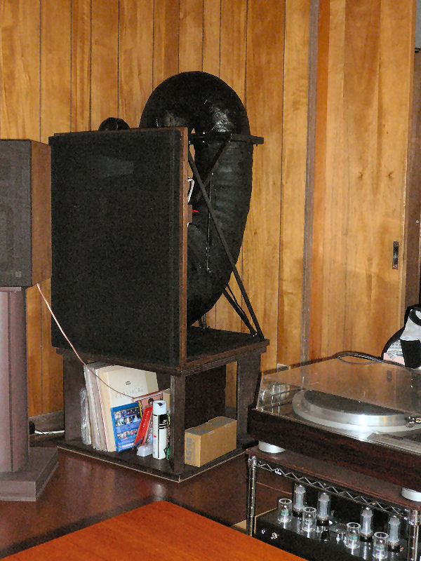
left in the living.jpg

However, the three-dimensional big lanterns of the Nebuta Festival in Aomori gave me a hint of easier way of making FRP ducts.
Thus I resumed building the sound muffling duct installed speaker system as in the photo. It took one month for designing and almost four months for building.
I started using them in July 2018.

-2/32-
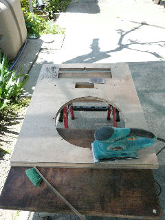
buffle sanding.jpg

Sanding of a buffle after making it two layered.
I had the plywood cut at the diy shop I bought it. I selected the shop for the board to be cut in exact sizes. However, I was unlucky this time with the person who cut my board. He made four wrong cuttings. I had to brought back two of them to be cut in right sizes. Of other two, I compromised with them and used as they were.
N.B.Nautilus is the product name of B&W.

-3/32-
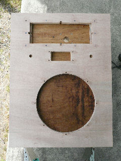
double layered buffle.jpg

The baffle with needed holes and openings aftrer being sanded down.
For marking holes for fitting screws I placed actual speaker units for marking. However, the attenuators and the tweeters couldn't be fitted. The board was too thick for them and I had to take amending measures.
I had to make the shafts of attenuators longer with adding pieces of same sized metal pipe. Of the tweeters, I couldn't fit them on the outside of the board. So they were fit on the inner side.

-4/32-
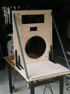
duct mount on buffle.jpg

A baffle and a duct rack temporarily joined for checking. The metal stays for shelves are not eternal.

-5/32-
selfadjusting nuts installed.jpg

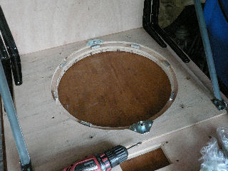
I had to make and install self-supported nuts for fitting woofers before completing ducts as they can't be reached for tightening after assembling the ducts.
I used alminum shaft fot making those nuts, installing a tapped hole in the center and two smaller holes for supporting nails on each piece.

-6/32-
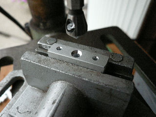
making selfadjusting nut.jpg

The photo shows how I processed an aluminum piece into a self-supported nut.

-7/32-
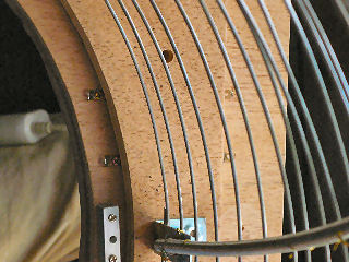
feeder and auto nut.jpg

The signal feeding terminals for a woofer and a self-supported nut are showing. The junction of the duct framework onto the rack is not yet treated.
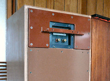
The duct framework is connected later to the baffle board using two nut-welded plates, four L-shaped metal fittings, and stainless net. The last was nailed and bonded to the board.
The board seemed to warp as I worked on it. So, I made all possible measures to strengthen the junction not to let it break when the duct rack is joined tight to the baffle board.
The signal feeders for woofers are made of cupper. They were installed along the 0.5mm-deep cuts on the baffle board made by a trimmer.

-8/32-
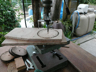
joint board for duct2-3.jpg

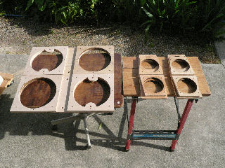
 Woodwork:joint boards

-9/32-

all duct joint boards.jpg

Making a smaller smooth opening on a joint board.
These are the joint boards used between ducts on which are mounted u-shaped flexible aluminium ducts.
You need a fret saw for cutting openings with projections.

-10/32-
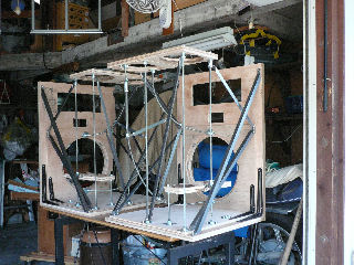
assembling joints and holders.jpg

Assembling all frameworks to check rooms for each duct.
It appeared at this stage that there were two points where ducts collide.

-11/32-
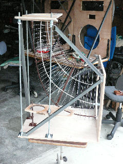
duct1 cage making.jpg

Making the framework of the first duct.
I used #16 stainless wire for the duct framework. Two 10mm-thick bolts and two 6mm-thick bolts I used for stays.
I expected that the framework can be easily made utilizing springy stainless wire but it was utterly contrary. It needed time and patience, killingly.
I added wire to make the basket framework denser after it was once completed to ensure safer FRP installing.
Wire is fastened onto stays at every crossing point adjusting it for the final surface to become smooth. However, the finish turned out to be bumpy on the surface.
The total length of the stainless wire came to 90 meters.

-12/32-
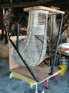
duct1 frp inside.jpg

Installing FRP inside the wire framework.
To tell the truth, I wasn't sure if my imaginary way of installing FRP was actually possible. So, I bought only 250g FRP material first for trial. It turned out okay and I ordered the total FRP materials.
I installed one layer of FRP inside the wire framework, two layers outside. The surface layer outside is made of a stretchy glass fiber knit with resin that contaied paraffin.

-13/32-
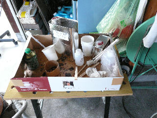
frp desk.jpg

My FRP workdesk
Tools were paper cups, a calibrated syringe, disposable chopsticks, painting brushes and waste cloth. I prepared cleansing liquid but it was useless.
FRP making was the repetition of preparing a cup of resin to be mixed with curing agent, placing a proper sized 10cm-wide glass mat onto the wire framework and applying polyester resin onto the mat to be soaked in.
I continued the work day after day for more than a week. Air temperature was higher and resin hardened quicker even with less curing agent. It was long busy work. Killing again.
On the first day I breathed in too much resin vapour and I felt sick that night. So, from the next day on I used two fans plus I did the work almost out of my workshop.

-14/32-
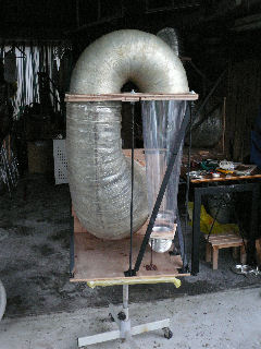
sizing duct2.jpg

As had been repeated with my past buildings, the components can never be accurately cut as designed.
So, my building is always accompanied by adjusting processes. Here is a second duct being adjusted with its length and angle.

-15/32-
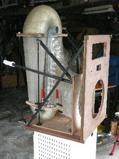
sizing duct3.jpg

Adjusting a third duct to be fitted.

-16/32-
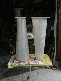
duct2 frped.jpg

Here are second ducts with their FRP covering finished.
The base cone is made of polyvinyl chloride sheet. They were polished by a wire brush and covered by double layered FRP.
The first layer is glass mat reinforced. The second by stretchy glass fiber knit. The surface was grinded to be painted.
The cone was connected to the board with a bonding agent and nails. I also drove nails for them to serve as anchors of FRP.

-17/32-
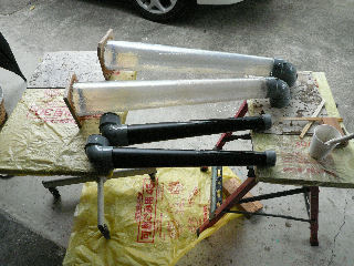
duct3 and 4.jpg

The third and the fourth ducts.
The third duct has only one FRP layer over the polyvinyl chloride cone as I judged the acoustic pressure is very low here.
The fourth duct is made of pvc pipe and elbow。

-18/32-
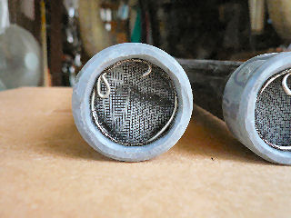
throat net.jpg

I installed net at the throat in order to stop bugs from entering.

-19/32-
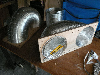
joint duct1 making.jpg

A junction between the first and the second duct. It is made of flexible aluminium duct to be covered with double FRP layers. The diameter of the duct is 20cm.
The junction between the second and the third cones is also made of flexible aluminium duct to be covered with a single FRP layer. The diameter is 10cm.
The diameters of these flexible ducts deviate from those in the original design. There were no actual ducts with diameters as designed in my plan. They were simply selected from among those sold at a diy shop nearby.
Making the first into a u-shaped junction was difficult as its radius was too tight.
These u-shaped junctions were connected to the board with a bonding agent and nails. I also drove nails for them to serve as anchors of FRP.

-20/32-
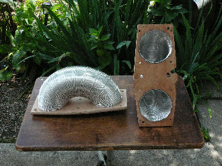
joint duct2.jpg

Installing FRP inside the wire framework.
To tell the truth, I wasn't sure if my imaginary way of installing FRP was actually possible. So, I bought only 250g FRP material first for trial. It turned out okay and I ordered the total FRP materials.
I installed one layer of FRP inside the wire framework, two layers outside. The surface layer outside is made of a stretchy glass fiber knit with resin that contaied paraffin.

-32/21-
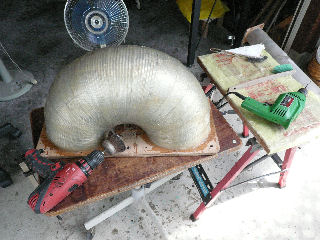
sanding joint duct1 frp.jpg

The flexible junctions were polished by a wire brush for painting. I found the polyester is very hard.
Other ducts were also treated likewise for painting.

-32/22-
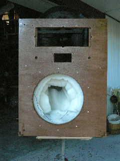
duct1 muffler installed.jpg

The first duct was lined with sound absorbing material thick inside. I worked overtime that day as I wanted to see how it becomes.

-23/32-
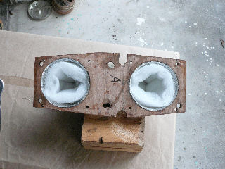
joint2 lined with muffler.jpg

The second u-shaped junction lined with sound absorbing material.
The junction board has an unnecessary hole and a cut for fixing it on the duct rack, for I placed the u-shaped junction on the wrong side and I had to added a new hole and a cut.
Other ducts were also lined likewise with sound absorbing material.

-24/32-
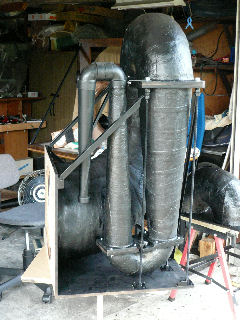
duct assembled.jpg

Final assembling
All the duct components were assembled on the duct rack. The black color was picked up as I wanted to finish the work any quicker by painting with only one color.
The duct rack is ready to be coalesced with the baffle board.
The long building work was coming to the end. I fond I was excited that day. I made a few smaller mistakes in my daily life.

-25/32-
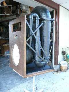
painted duct mounted.jpg

The duct rack coalesced with the baffle.
The remaining work to be done in my workshop was to install a speaker network and attenuators.
However, I had to lengthen the shafts of attenuators before their installation.
On top of it, I found at this stage there was no proper space for an attenuator box to be fitted behind the baffle board. I had to give up fitting one encased in a plastic box. It was only possible to fix one naked. Thus the day passed without actually installing them.

-26/32-

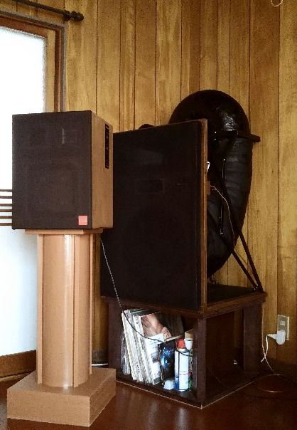
left in the living.jpg

Overcoming such last unexpected troubles I almost finished "nautilus diy version" and placed them in the living room.
Carring them was another problem. The distance from my workshop to the living room was about 20 meters. The path was narrow and there were many potted plants. So the path had to be cleared first.
The system was too heavy for me to carry in my arms. So I had to make a temporary rack to carry them by a two wheeler we luckily had.
Old man I was, I could carry and set them to the room alone at last. Well done!

-27/32-
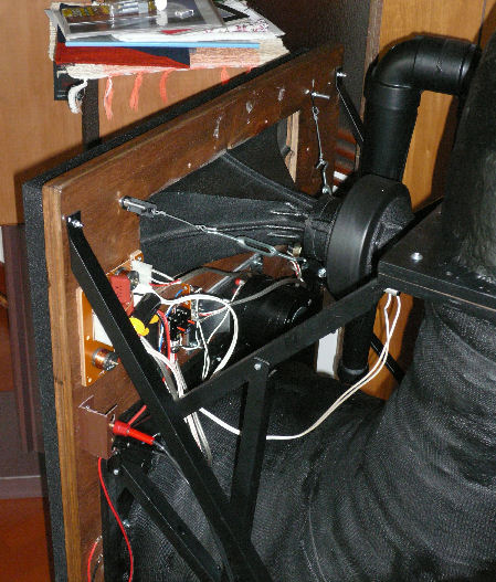
behind buffle up.jpg

Behind the baffle.
I couldn't encase the network as I mentioned above.
The weather had taken my side while I kept on building them for about four months. Even during the last one month in the rainy season, it rained only one day or two when I gave up building them. Lucky I really was.

-28/32-

Supplement:Network encased.
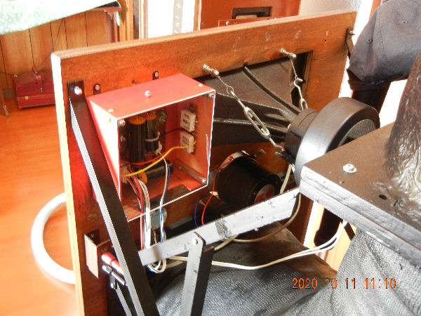
2 revised network installed.jpg

More than three years had passed since the system was completed and I could finally made cases into which I put network devices. Please visit here for details.

―Supplement―

Review


Review
Compared with the sound of "EV speakers and Yamaha cabinets" the sound is lucid.
This is what I expected most to this speaker system, which is very reasonable because the sound is not blurred by the sound from the reflex ports.
This characteristics, of which tendency is shared by my buhsp1 system is much more obvious. That is, the sound in the duct is free of cross-mode propagation whaeras with buhsp1 such propagation, theoretically, might be happening because its duct covers all the sound range.(to be continued)

-29/32-

Review


Conclusion: The sound is lucid and delicately expressive. It is so natural that you'd assume the sound is born there without speakers.

-30/32-

Postscript

Postscript
There were very many items to make. The building days were the days of perseverance. The processes looked never progressed.
The making the frameworks of Duct1 and giving FRP on them was difficult and time consuming work which I had never experenced before. It required perseverance so much that I felt a foreboding of good performance.
Not all the processes turned out as planed but I could tackle each deviation and the finished makeup was within my original imagination.

-31/32-

Data
● Ducts
Duct1: made of stainless wire(#16) + three FRP layers
Duct2: hard polyvinyl chloride sheet + two FRP layers
Duct3: hard polyvinyl chloride sheet + one FRP layer
Duct4: polyvinyl clolide pipe and elbow
● Network: Cross over 800Hz、6000Hz(diverted from Technics SB-7)
● Tweeter:EV T350 3.5kHz~15kHz ±3dB
● Squawker:JBL horn(2730A horn + 2426 driver)800 Hz~20 kHz response
● Woofer:Radian2216 40~3.5kHz voicecoil diameter 10.5cm

-32/32-
End of Nautilus D.I.Y.

Return to the list


Back Unloaded Horn Speaker -1-
(BUHSP1)

●"Internal volume enlargement & repainting" newly added on 2018/10/15.here

Preface Skip Preface
A back unloaded horn speaker (hereafter cited as BUHSP) is not a mistaken use of a back loaded horn speaker. It is natural if you have never heard of it, for the naming is mine.A BUHSP is a speaker which muffles the sound behind the diaphragm and, by so doing, produces a more high-fidelity sound in front.
In other words, it is the speaker in which the space behind the diaphragm becomes a virtual boundless space.
The idea was faithfully realized in Nautilus some twenty years ago, and B&W has succeeded to the technology.
My BUHSP is a speaker to which is applied the idea in a way much simplified. However, the result was satisfactry. I, therefore, introduce it here as a very hi-Fi speaker.

-1/20-

finish outlook.jpg

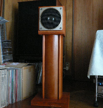
The photo shows a BUHSP1 in my living room with an ordinary bass reflex speaker behind.
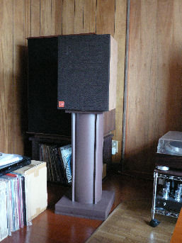
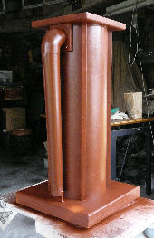
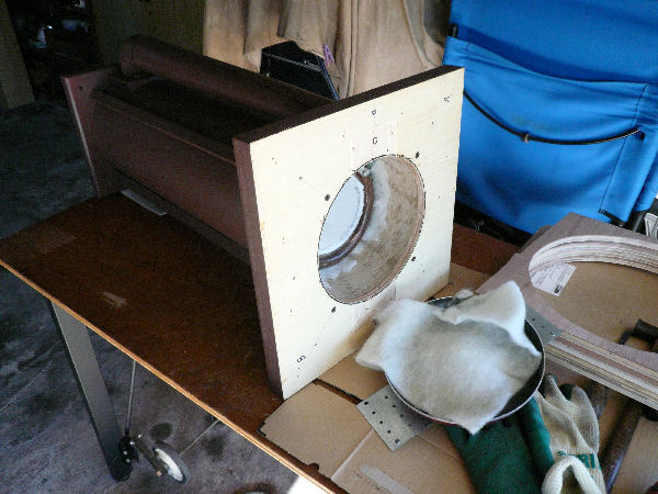
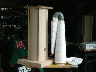
The BUHSP consists of a square cabinet that contains speaker units, a columnar duct in which is installed a half of the inverted U shaped horn and the base on which rides the duct with the cabinet on top. The duct functions itsel a part of the muffling horn, too.
The total length of the muffling horn is about 1.5meters and the height of the speaker is about 1 meter.

-2/20-

cross section view.jpg

How does the unloaded horn works?
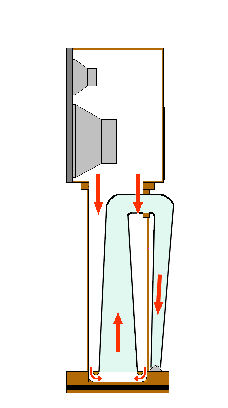
Outline: The sound behind diaphragms propagetes in the cabinet as well as down all the way in the unloaded horn(*see the illustraton).
In short, the sound is muffled in the unloaded horn without reverberation, thus giving no stress to diaphragms from behind.(to be continued)

-3/20-

Explanation: The columnar duct gets narrower in space toward the bottom because it contains a part of inverted U shaped horn which gets thicker toward the bottom.
Thus the duct and the inverted U shaped horn in total make one tapering tube which I call 'unloaded horn.'
The sound propagates first in the cabinet, then in the columnar duct to the inverted U shaped horn in an instant(the speed of sound ≒340m/sec). As the sound propagates all the way to the throat, it is muffled to the extent that it is barely audible at the end. I actually tried to listen to the sound at the throat to which putting my ear and found the sound was indeed very small.
In Nautilus, the sound is treated in four ranges. On top of it, the woofer is fixed in a nautilus shaped tube, in which the sound may propagates more smoothly as well as muffled more effectively.
My BUHS treats the sound with only one muffling horn and also, propagation changes directions more than three times. However, the muffling effect of the BUHS, as I myself confirmed it, was practical enough to liberate diaphragms from the stresses they usually get from behind. A BUHS thus can reproduce sound with satisfactory fidelity.
You can learn more about the technology at the B&W web site.

-4/20-

duct1.jpg

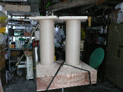
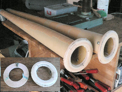
The photo shows the process of making a columner duct. It is a container of a part of U shaped horn while it is a part of unloaded horn itself.
On to the duct ends are fit wooden plates made of multi-piled plywood. The hole must be right sized so that the duct is lightly hit to be driven all the way into the hole to ensure sturdiness.
Material of the duct is pressed paper. Such columner pipe is called void pipe or cardboard tube. I bought it at Kometani Shikan Manufacture Co.Ltd. They sell their products in 4m long. They cut pipes to order, but you have to buy a whole pipe.

-5/20-

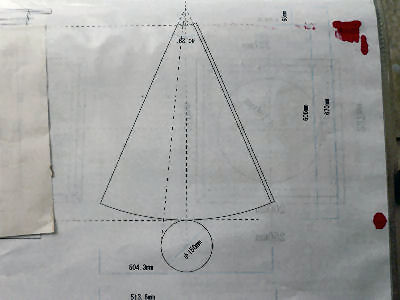
cone design.jpg

The photo shows a full-sized design of an old horn. The generating line is 600mm and the diameter of the circle at the bottom end is 150mm.
Red stains are made while printing. They have nothing to do with the design.

-6/20-

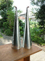
cones1.jpg

The photo shows old horns made to the design above. Materials are galvanized iron sheet and 13mm copper elbows.
The muffling effect was confirmed but to increase it I designed the second horn with which to replace the first as shown in the following photos and colums.

-7/20-

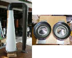
inner horn bottom disk m.jpg

Left: An inverted U shaped horn about 1.5m long with a 45mm caliber throat. The length is about two times as long and the throat caliber is about three times as big.
Materials are PVC sheet and pipe. To the bottom end is attatched a funnel made of wood.
Right: Plates(original) which are installed at the bottom of the duct in order to reflect sound smoothly. They are made out of aluminum frying pans and galvanized iron sheet

-8/20-

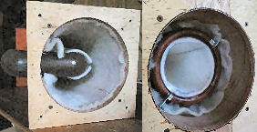
horn top bottom view m.jpg

Left: Top end view into the duct
Right: Bottom end view into the duct

-9/20-

horn 1st painted.jpg

The photo shows an assembled undercoated unloaded horn.
Before finishing painting, at the bottom base is added an iron plate which weighs about 8kg to make the horn stable as well as to make the sound tight.

-10/20-

cabinets.jpg

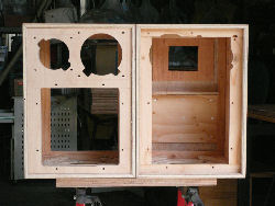
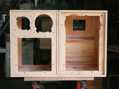
Cabinets(W:330mm H:460mm D:310mm), in which are fixed speaker units, are made with 12mm plywood double piled.
On top of it, libs are installed to any larger flat surfaces and every corners are shored up with triangular prismatic wood as necessary steps to avoid cabinet resonance.
A cabinet when completed was rather heavy but the total weight of the speaker was not heavy enough for heavy bass sound. To compensate it, I fixed another iron plate on the back of each cabinet as shown in the photo below.

-11/20-

frame painted m.jpg

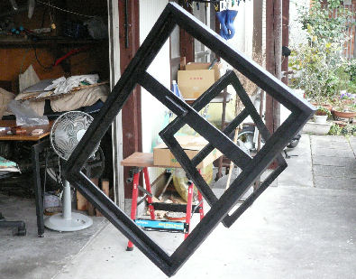
Left: Net frames under making. To make a frame flat, it was cut out of a plywood board. It is designed to fit on the cabinet by a piece of magnet.

-12/20-

wight attached m.jpg

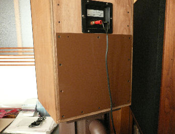
The photo shows the iron plate fixed on the back of the cabinet. It is 6mm thick and about 4kgs weigh.
The plate was added after it was completed. For, after listening to a while, I judged the bass sound is loosened. I learned it is a weakness of a tall speaker.

-13/20-

weight mounted m.jpg

Additional Comment
The improvement of Buhsp Experimental was more than I expected.
Judging from the result, I surmised that the woofer of BUHSP is larger than that of the experimental and the mass of the former is still not enough. Therefore, I mounted another weight at the upper part of the back panel. (I added a new comment on the sound in the review at the bottom.)
The whole system became very heavy. Each time I slide it as I clean the room, I feel it. I attached a fitting to the weight in order to chain it to the wall against an earthquake.

-14/20-

throat new anchor.jpg

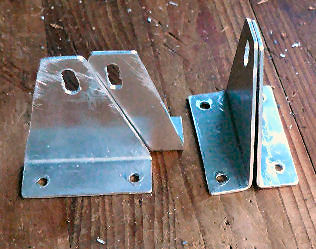
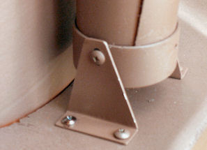
Throats were first fixed with small L-angled fittings but they were unstable. To fix them firmly, I made triangular staplers as shown in the photo.

-15/20-

new anchor installed.jpg

Throats were fixed firm on the base.

-16/20-

finish1.jpg

The photo shows the size of the cabinet is minimum to the mounted three units.

-17/20-

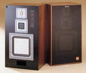
apm-55w m.jpg

Sony APM-55W
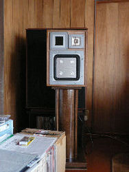
The original seaker system which was put on the market around 1983. I bought a set of them through an auction. They were old and full of scars and dents. I had woofer edges renewed.

-18/20-

Review


Review
In comparison with a bass reflex speaker I have, the sound of a BUHSP is, as a whole, clear and pure and more expressive in detail. Such characteristics may sound to you a bit solid.
A bass reflex speaker uses the sound behind the diaphragm which is opposite in phase, reversed and mixed with the front sound (thus making the lower tone more voluminus). The reversed sound blurrs the outline of the original sound and also charges unnecessary burdens on the diaphragm. Such sound may be softer and more comfortable to your ears but less faithful to the original sound.
I repeatedly listened to both speakers and compared their sounds. My conclusion is that your choice is free depending on what you want. It is like the choice between the song you sing in a bathroom and that you sing outside.
To those who want to relax, a bass reflex speaker may sound more comfortable while to thosewho, such as me, want more hi-fi sound, a back unloaded horn speaker may sound more satisfactorily. I personally choose the latter. I am fully satisfied with my BUHSPs which sound clear, dimentionally deep and naturally real.

-19/20-

Review


Review
There wasn't a dramatic effect as with "EXPERIMENTAL."Perhaps because BUHSP was already almost completed? However, mounting another weight brought qualitative change in sound which was very important. It was a kind of change to be attained after the last one step. The mounting of the weight was the very last step!
Together with the increased clarity, the sound makes you feel you are at a live performance much more than before. A good sound turned out to be a natural sound after all!
I have found it especially true when I listen to a live recorded concert or an on-the-spot broadcasting of NHK Symphony Orchestra. It was my luck, too, that I recently restored an old Pioneer TX-6300.
To tell the truth, it was out of my expectation that the equipment I build would provide such a superb performance. I have had continued building my audio equipment without any clearimage of goal but luckily I judge I could have attained the height of goal which can be recognized only by those who attained it. I have been using 6AH4 amplifier, these days. (Written on May 21, 2016)
My bass reflex speaker cited above:
Tweeter EV T350
Mid-range JBL2730A+2426
Woofer RADIAN2216(38cm)
Cabinet YAMAHA

-20/20-

Return to the list

"Internal Volume Enlargement & Repainting" added on 2018/10/15.

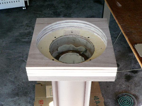
bottom opened.jpg

I had been knowticing that BUHSP2 system sounded better in lower sound than BUHSP1. The only notable difference between the two systems is a larger internal volume in the bottom base of the former, where the downward propagation changes its direction upword. Thus I finally set about the renovation of the latter.
I opened the base and took off the reflection disc made of a frying pan.

―21/20+4―

plates added.jpg

As the photo shows I added four pieces of plywood board with a larger hole of about 3.6 liters. I discarded the disc and filled the hole with sound absorbing material.
I glued the board one after another fixing each with nails. However, the next day I found gaps between boards which I couldn't correct perfectly. The last remedy was to apply polishing powder into gaps before painting.
In the photo the duct looks like new but it's not. It's chololate color reflecting direct sunlight.

―22/20+4―

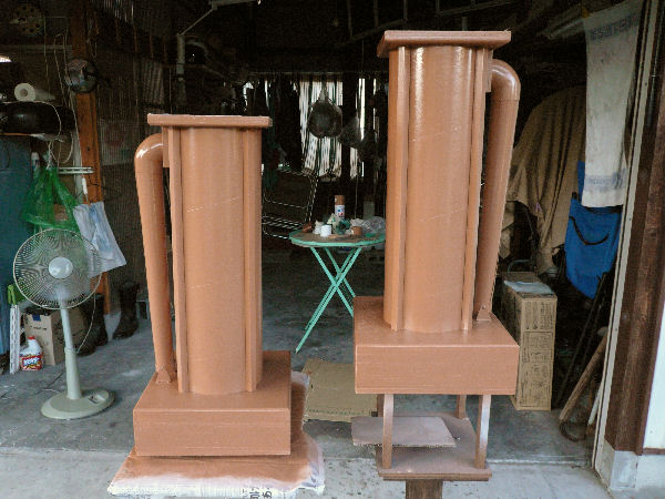
re-painted.jpg

The internal volume enlargement work finished a pair of the base'n ducts are repainted.
They are painted for the third time. The former chacholate color was too bleak but it seems this ocherous is another mistake. White under coating unexpectedly made it too light.

―23/20+4―

renovation finished.jpg

A renovated BUHSP1 infront of a Nautilus D.I.Y. The thicker base makes it look well-proportioned.
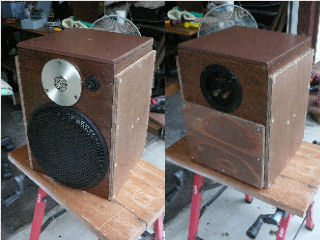
More important the sound improved as I expected it to be. It is just like that of the Nautilus D.I.Y., only with the amp volume slightly adjusted as it is less efficient.
Learning Through Experience: The inner volume of the cabinet as well as that of the base can not be minimized. They need certain amount of volume.   

―24/20+4―
End of BUHSP1


Back Unloaded Horn Speaker -2-
(BUHSP2)
An Application of Back Unloaded Horn to A Speaker System on The Market

.jpg

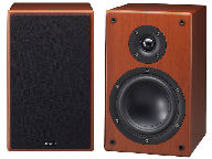
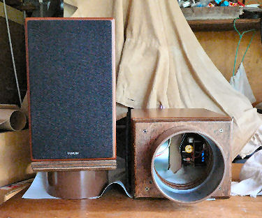
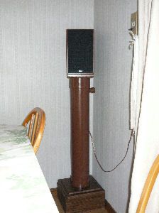
The top photo shows DENON SC-107SG, a conventional bass reflex bookshelf speaker system.
I converted them into a set of back unloaded horn speakers.
How were they converted?
I bought them many years ago which I had used in my study for some time until I had had an opportunity to listen to open box speakers. Their sound was unconstrained and very natural. I had never heard such sound before. I was only ignorant that the sound of DENON SC-107SG was so constrained.

-1/10-

cone with funnel.jpg

Chief materials for the conversion:
1.Cardboard pipe for a carpet core. Calibar ≒ 80mm.
2.PVC pipe (nominal diameter 130)
3.Remainder wooden material
The photo shows the horns with funnels attached.
Cardboard pipes were processed into tapered horns.

-2/10-

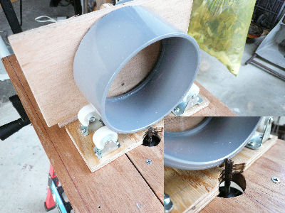
pipe cutting jig.jpg

I made pipe cutting tool for PVC pipes and sockets had to be cut vertically against its generating line in order that the speaker, when finished, must stand vertically.
The tool, however, didn't work right because of the backrushes of rollers. I had to practice to have a satisfactry result.

-3/10-

cabinet hole cut.jpg

Hole cutting of no return!
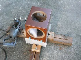
The cabinet is molded wooden fiber. It was set with a cushion on the fixing tool for the hole to be cut manually.

-4/10-

SC-F107SG ready.jpg

PVC sockets fixed to cabinets.
The hole must be right sized so that a PVC socket is lightly driven all the way into the hole to ensure sturdiness.
A part of network can be seen inside. Electrical parts used for the network were of good quality.

-5/10-

horn bottom inside.jpg

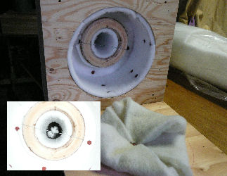
Above: Bottom end of horn.
Sound absorbing material is attached inside. The inside horn is sticking out into the bottom space.
Below: Upward view into the horn.
Absorber is hung vertically in the center of the upper part of horn.

-6/10-

horn top inside.jpg

Top end of the horn on which a cabinet sits.
The sound absorber reaches the inside of cabinet bottom.
A cabinet can be turned to any direction. It sits tight without backlash nor sound leak.

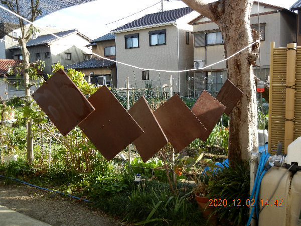
-7/10-

horn painted.jpg

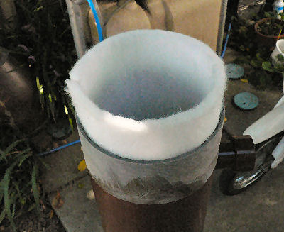
Side view of the horn drying paint.
A navel at the upper end is the throat. A piece of net is installed in it to stop insects.

-8/10-

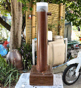
finish.jpg

The photo shows DENON SC-107SG with back unloaded horn installed. Cabinet is about as high as your ears.
You can set the cabinet to any direction. That is, the speaker can be placed just at the corner as shown in the photo.

-9/10-

Review
The constrained sound disapeared. The application of a back unloaded horn was successful. It revealed the original potential that DENON SC-107SGs had, producing clear, dimentionally deep and so natural sound.
Sitting in fron of these speakers in midnight hours, listening to a FM disc jockey, for instance, you'd feel like listening to it forever.
It is unsuitable for a high powered big heavy bass sound though, by making a cabinet much heavier, it'd become more suitable for such sound, too.

-10/10-

Return to the list


Back Unloaded Horn Speaker -Trial Version-

experimental_1 m.jpg

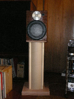
Back unloaded horn speaker system I built for the first time.
Here are some experimental processes which finally led to the 'BUHS (BACK UNLOADED HORN SPEAKER) system -1- & -2-
The photo shows an embodiment of my idea of a vertical back unloaded horn speaker system (hereafter cited as BUHSP).
A cabinet, in which is installed a speaker unit, is mounted on top of a colum that functions as a vertical back unloaded horn(hereafter cited as horn).
My heart had been filled with expectation for a very good sound it would produce but the result was disappointing.
Naturally(?), I had no idea what was wrong with the system. The only choice given to me was to go on improving it believing its potential.
Luckily, I could successfully attain it following the steps as shown below.
●"Internal volume enlargement & repainting" newly added here.(2020/12/7)

-1/12-

edge jig 1+2.jpg

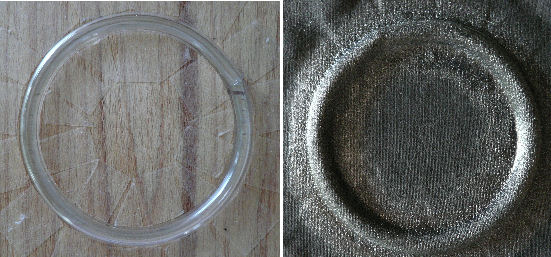
The unit installed in the cabinet is a coaxial 2-way flat speaker taken from Technics SB-RX30. The edges were made of urethane and were badly tattered. So, I replaced them with new ones I made them with cloth by myself.
The photo shows how I made them having consulted with some web pages.
A pair of cabinet, though I built them after a great toil, were used only when they were tried. Their sound was very poor and they had been put in storage since then.

-2/12-

test m.jpg

New cabinets The photo,though the time it was taken is out of sequence, shows a new cabinet mounted on the horn. The colum is made with a piece of paper pipe.
Now, how was the sound improved?
The sound was improved but not satisfactorily. That is, the horn must be improved in turn?!

-3/12-

cones1.jpg

Improvement of the horn
The photo shows the original inner horns, which were installed in the colum lined both inside and outside with sound absorbing material.
Were they not long enough?
I made a pair of new horns as in the next photo.

-4/12-

inner double cone m.jpg

In B&W, they managed the size smaller making it into a nautilus shape. I once tried it myself but gave up as I hurt my arm. So I made it longer as shown in the photo.
The sound was much better!
The second cabinet and the horn were successful, only except a cheap kind of resonance that seemed to come from the shin cabinet.
The cabinet must be improved more!?

-5/12-

new cabinets.jpg

So, I built a pair of new cabinet as shown in the photo before improving the cabinet in the photo 3.
The sound of the new cabinet in the photo and the corn was satisfactory! It means the horn was good, too.
The new cabinet was made with double layered plywood board and ribs installed in every needed place. On top of it, the corners are all reinforced with triangluler wood.
I had a feeling that I had got the knack and I built another version of a longer horn to complete SPEAKER(BACK UNLOADED HORN) -1-.

Let me come back to the improvement topic. I judged the horn in the photo above is good enough to be used. That is, my job left is to improve the thin cabinet.
The followings are the steps of improvement, though the actual handiwork was done much later.

-6/12-

reinforcing panels m.jpg

Improvement of the thin cabinet
There were two points for the improvement.
One was to stop resonance by thickening the cabinet board adding another layer of 12mm-thick plywood.
The other was to stop losing vibration energy as possible.
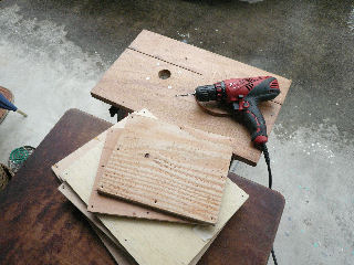
The photo shows additional boards being cut.

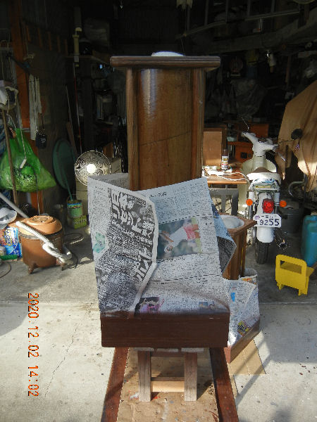
-7/12-

drying panels m.jpg

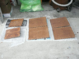
The photo shows the boards being dried after painted.
A tall speaker system, such as my BUHSP, by nature, has a congenital defect that it loses some vibration energy generated by a diaphram because it easily sways counter way reacting the movement of the diaphram.
As a measure for the latter defect, I mounted a 9mm-thick steel plate that weighs about 4.4kgs on top of the cabinet.

-8/12-

/reinforced f and r m.jpg

Improvement done!
The photo shows the finished cabinets.
You may say they look ugly. They are! But the original cabinet boards were glued and the only way of thickening the boards was to add boards outside. The most important thing was the improvement of the sound which was attained at last!

-9/12-

reinforced finished m.jpg

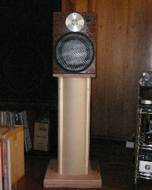
The photo shows the finalized system placed in my study.
At first, the sound was poor but after taking improving measures, the sound became so good as I judged there might be no better sound.
This speaker system is driven at this moment by 71A single amp.
(This articlr was written on 10th April, 2016)

-10/12-

Postscript
Trying to apply the tapering tube theory to a vertical horn, I have built a few set of BUHSP, which were different in appearance but alike in nature to 'Nautilus' manufactured by B&W. I started working without enough knowlege nor understanding but enjoying woodworking.
Though I could finally complete them successfully, the result had not been ensured and buying old speaker units, which were expensive to me, was an adventure. There were, actually, a few units I bought and didn't use.

Lessons I learned through building BUHSPs
1. The thicker and the heavier the boards of speaker cabinet are the better.
2. A speaker cabinet needs a certain capacity, or a minimum sized cabinet that can barely contain units and a network is useless.
3. The longer the length of a horn is, the better but the size can be compromised.
4. For a tall speaker system, the heavier the mass of the cabinet, the better. Because such a speaker system, by nature, has a fatal defect that it loses some vibration energy generated by a diaphram because it easily sways counter way reacting the movement of the diaphram (already partly described above). (to be continued)

-11/12-

Postscript (continued)
The phenomenon was conspicuous in lower sound. The effect of installing a heavy steel weight to cancel it was obvious.
5. Generally speaking, a flat speaker unit makes good sound but not cheaper ones.
6. I could train and brush up my woodwork skill.
7. An old speaker network can be restored to an original(?)performing condition by replaceing old capacitors with the new.
I restored the networks of Technics SB-3A and APM-55W. Judging from the rich bass sound and the unconstrained high tone, they are functioning at their best.
8. My BUHSPs gave me an equipment with which I can enjoy listening to music in a (more?) HiFi sound. Such HiFi sound, which I enjoy almost every day, in turn, has trained my ear to discern noance in sound. I now enjoy each sound of a key pressed by Martha Argerich, my favorite pianist. It's a new feeling to me which I couldn't have imagined before.

-12/12-

Return to the list
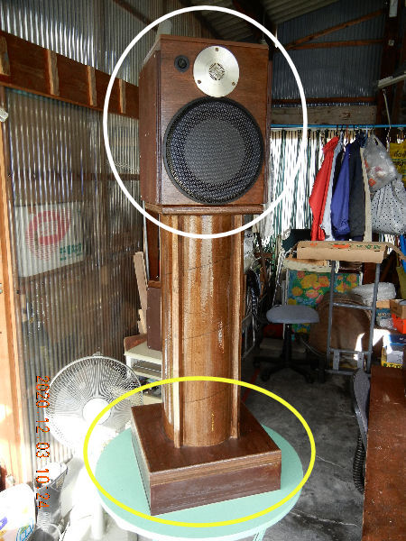
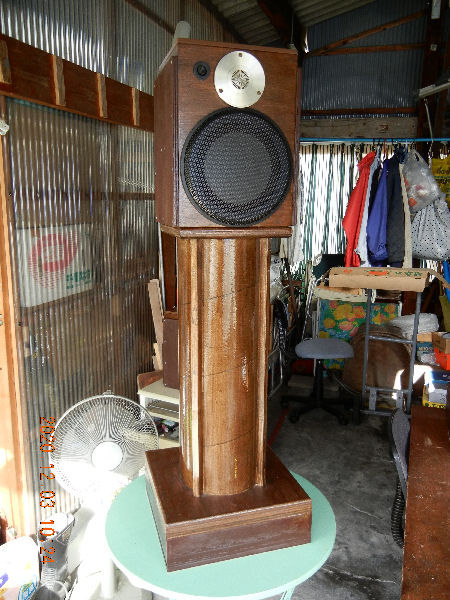
9-2reformation almost finished.jpg
I finally got to the improving work of the BUHSP trial version. The system had been left to become the last unimproved system.
The photo shows the system temporarily assembled at my workshop after the improving work. The top cabinet in the white circle was repainted and the base in the yellow circle was enlarged by some six liters in the inside space.

―13/12+12―

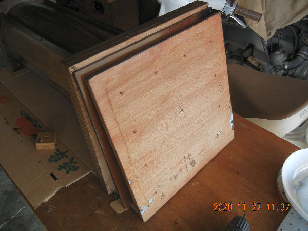
1-re-opening the bottom.jpg
The work started with taking off the bottom lids that were consisted of a steel and a plywood panel.

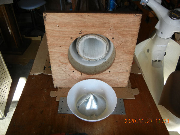
―14/12+12―

3-taking off the reflector.jpg
Inside the bottom space had been installed a propagation reflector. It is to be done away with as they were done with when BUHSP1 was reformed.

―15/12+12―

4-materials for the reform.jpg
It'd been nearly one year since I had prepared these materials.

―16/12+12―

5-ribs to the enlarged bottom.jpg
Side planks with 6cm wide are glued to the base upward strengthened with triangular sticks that were glued and screwed.

―17/12+12―

6-sound absorbing material 1.jpg
The bottom end of the horn was stuffed with sound absorbing material.

―18/12+12―

7-sound absorbing material 2.jpg
The enlarged space was also stuffed with sound absorbing material.

―19/12+12―

8-closing the  enlarged bottom.jpg
To close the bottom space I newly cut out a plywood board to screw it upward to the side planks to which the original bottom lids were screwd. I didn't glue them for the future re-opening. The base was stoutly finished.

―20/12+12―

9-painting of reinforcing panels.jpg
The photo shows the cabinet einforcement boards being dried after re-painting.

―21/12+12―

10-painting enlarged base.jpg
Painting the enlarged base.

―22/12+12―

11-reformation almost finished.jpg
The photo shows the system temporarily assembled at my workshop after the improving work. The system was finished as I had imagined it to be.

―23/12+12―

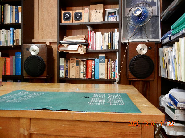
12-set back in the study.jpg

The reformed BUHSP trial version system was againg set in my study.
Was the reformation successful for the better sound? Here is some impression I gathered.
As a whole the sound was clear enough as it should naturally be with a back unloaded horn speaker system, and also the sound was so vivid as it should naturally be with the disk speaker system. The lower sound is not as ample as that of a big woofer system. However, with a Jazz you can enjoy comfortable bass sound.
I'm writing this with a classic piano music played. It makes me feel very happy as if someone is playing the piano for me in the same place.

―24/12+12―
Return to the list